FIELD ORIENTED CONTROL MOTOR DRIVER
Field oriented control is the most efficient and powerful way to drive a brushless DC motor because it maximizes motor torque by keeping the rotor flux and net current vector perpendicular and by always supplying two of the three phases. However, the drawback to this method is that it is more complex than other commutation strategies. This section will go into the theory behind the control strategy
.
Essentially field oriented control is simply a voltage controlled current control loop. However, dealing with three variables, the three phases, and with a rotating target, the rotor flux, this becomes more complex. Luckily for brushless DC motors the method is a bit simpler because the rotor flux angle is equivalent to the rotor angle because the motor is a synchronous machine. There are also two mathematical transforms that can make the motor commutation more streamline. The Forward Clark transform is used to convert the three phase current vectors into it’s equivalent two orthogonal vectors. By doing so only two variables are regulated by the control loop instead of three. Below are the Forward Clark transformation equations.

However, the control loop continues to have a rotating target, which can be removed by using the Forward Park Transform which puts the observer on the rotating reference frame. Now instead of trying to regulate two oscillating variables, only two DC variables are regulated. Not only does this transform make the current regulation simpler but it also improves computational speed, allowing more accurate current sensing and motor commutation. Below are the computations required for the Forward Park Transform.

These transforms can be better understood visually, below is a diagram depicting the reference frame and the regulated signals without any transforms, after applying the Clark transform and after applying the Clark and Park transform.
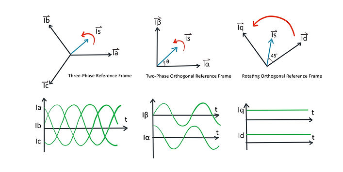
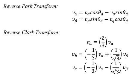
With the transforms complete, the measure currents are compared with the desired currents and an error signal is generated. Current iq is always set to zero and id is set depending on the amount of torque desired. The error signals are then used to generate a correction voltage but before it can be modulated onto the motor, the Reverse Park and Reverse Clark transform have to be performed to convert it back to a three phase reference. Below are the equations for the conversion. .
This commutation strategy is heavily dependant on the accuracy of the rotor position and current measurement which is why careful deliberation was put into part selection.